
Quick Answer
Machine control systems automate or guide earth-moving equipment to meet design grades without manual staking. 2D laser systems use a rotary laser reference plane and achieve ±1/4-inch vertical accuracy for flat or single-slope work. 3D GPS systems use RTK GNSS and digital terrain models to control any surface and achieve ±1-2 inch vertical accuracy. The Trimble GCS900, Topcon 3DMC, and Leica iCON are the dominant systems on commercial grading projects.
Machine Control System FAQ for Grading Contractors
2D vs 3D Machine Control
2D machine control uses a rotary laser level to establish a reference plane. The system measures how far the blade is above or below that plane and displays cut/fill on the cab display or automatically adjusts the blade. 2D is accurate and simple for flat work, parking lots, and simple single-slope pads. It cannot handle complex 3D surfaces, cross-slopes, or varying grades across a site.
3D machine control uses RTK GNSS (or a total station) to know the blade's exact position in space and compares it to a digital terrain model (DTM) loaded into the system. The system displays or executes the cut/fill needed to reach design grade anywhere on the site. 3D is more expensive and requires DTM preparation but eliminates nearly all manual staking for grading work. See the machine control guide for a full comparison.
System Components
A complete 3D GPS machine control system includes: one or two GNSS antennas mounted on the machine, an in-cab control box (Trimble CB460, Topcon MC-X3, Leica MC1), mast-mounted receivers, a base station or network RTK correction source, and field software for loading design files. 2D systems replace the GNSS components with a laser receiver mounted on the mast and a sensor that measures mast extension height.
Frequently Asked Questions
What is the accuracy of a 3D GPS machine control system?
3D GPS machine control with RTK corrections achieves ±1-2 inches (25-50mm) vertical accuracy at the blade under good conditions. Horizontal accuracy is ±1-2 inches as well. For finish grading to tighter tolerances, verify with a total station or laser level after machine work. See the machine control accuracy FAQ for a detailed breakdown.
What is the accuracy of a 2D laser machine control system?
2D laser machine control using a rotary laser reference and mast-mounted receiver achieves ±1/4-inch vertical accuracy at the blade — significantly tighter than GPS. This makes 2D laser preferred for concrete flatwork and finish grading on simple slopes where a laser plane covers the entire work area.
What design file formats does machine control software accept?
Most machine control systems accept LandXML, DXF, and system-specific formats (Trimble TML, Topcon TP3, Leica LHD). LandXML is the most universal exchange format for digital terrain models. Your civil engineer or project designer should provide the DTM in LandXML format for loading into the machine control system.
Do I need a base station or can I use network RTK with machine control?
Both work. A base station on a known control point provides corrections via UHF radio — reliable and zero recurring cost, but requires setup and maintenance. Network RTK via cellular eliminates the base station but requires a subscription and cellular coverage on the job site. Many contractors use a job site base station for primary correction and network RTK as a backup.
How do I load a design file into a machine control system?
Transfer the DTM file to a USB drive or SD card and insert it into the in-cab control box, or transfer via Bluetooth or Wi-Fi if the system supports it. In the field software, select the project and design surface, confirm the coordinate system and datum match your control points, then verify the surface loads correctly by checking known elevation points on the design. Incorrect coordinate systems are the most common cause of design file errors.
What is the difference between indicate and automatic machine control?
Indicate (or "indicate only") systems display the cut/fill needed on the operator's screen but do not move the blade — the operator makes all blade adjustments manually. Automatic systems actuate the blade hydraulics directly through an electrohydraulic interface, keeping the blade at design grade continuously. Automatic systems are faster and require less operator skill, but cost more to install and maintain.
Can machine control replace grade checkers and surveyors?
Machine control significantly reduces the need for grade stakes and grade checkers during mass grading. However, final grade verification by a surveyor or grade checker is still required on most commercial projects, especially for subgrade and base courses that will be covered by pavement. Spot-checking machine work with a total station or laser throughout the project catches drift before it becomes a problem.
What is mast setup on a GPS machine control system?
The GNSS antenna mast is mounted on the machine, typically behind the cab on a dozer or on the blade mast on a motor grader. The offset from the antenna to the blade cutting edge must be measured and entered precisely in the system — any error in this offset directly translates to blade elevation error. Mast calibration checks should be done after installation and whenever the mast is repositioned or the blade is replaced.
How do I calibrate a machine control system?
Blade calibration involves moving the blade to a known elevation (survey shot by a total station or level), then confirming or correcting the system's computed blade elevation in the software. Some systems have automatic calibration routines. Cross-slope calibration checks that the system correctly reads the blade's cross-tilt. Calibration should be verified at the start of each project and after any major maintenance. See the equipment calibration FAQ.
What GPS machine control system is best for a dozer?
The Trimble GCS900, Topcon X-53x, and Leica iCON grade are the three leading systems for dozer applications. All three support automatic blade control with single or dual-antenna GNSS. Selection often depends on the contractor's existing software platform and support network rather than technical differences — all three are production-proven systems. Express Tools carries components and accessories for all major systems.
Can machine control be used on an excavator?
Yes — excavator 3D machine control is widely used for mass excavation and utility trenching. Excavator systems use IMU sensors on the boom, arm, and bucket to compute bucket tip position and compare it to the design surface. GNSS provides the machine's absolute position; the IMU sensors track the arm geometry. Common systems: Trimble Earthworks, Topcon X-53x, Leica iCON excavator.
What happens when the GPS signal is lost on machine control?
When RTK fix is lost, most systems switch to indicate mode (no automatic blade control) and display a warning. Work should pause until fix is re-acquired if operating in automatic mode. For network RTK users, check cellular signal. For base station users, check the base is operating and the UHF link is active. Most fixes reinitialize within 60 seconds of re-acquiring signal.
What is a digital terrain model (DTM) and how is it created?
A DTM (digital terrain model) is a 3D mathematical surface representing the design grade — a mesh of triangles connecting design elevation points across the site. Civil engineers create DTMs from the design drawings using software like Civil 3D, Bentley OpenGround, or Trimble Business Center. The DTM is the design surface the machine control system targets. Quality of the DTM directly affects quality of the finished grade.
How does machine control handle a site with multiple design surfaces?
Most machine control software allows loading multiple design surfaces — subgrade, base course, finish grade — and switching between them in the field. Operators select the active design surface for their current work phase. Having all surfaces in the system eliminates the need for separate grade staking at each phase and reduces sheet coordination errors.
What is the cost of a 3D GPS machine control system?
Factory-installed 3D GPS machine control systems cost $30,000-70,000 per machine depending on the manufacturer, machine type, and whether automatic control is included. Aftermarket systems installed on existing machines run $15,000-40,000 depending on the system and machine. ROI is typically 1-2 seasons on heavy grading work through reduced staking, grade checking, and overcut costs.
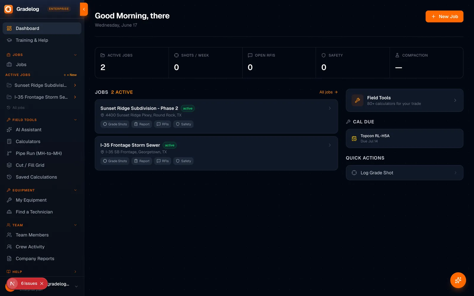
Managing machine control setups and grade verification on active grading jobs? Gradelog provides field documentation, control point tracking, and daily production logs. Free to start at gradelog.com.